Linux 2.6.35有Google大神的程式碼了!! (跪拜0rz......)
其主要提升網路封包處理速度
詳見: Linux 2.6.35 Includes Speedy Google Code, Less Bloat
2010年8月13日 星期五
2010年8月11日 星期三
[打造簡易作業系統 - 以GNU Assembler組合語言撰寫] (二) Boot Loader + 作業系統載入實例 (QEMU)
繼上篇說明如何撰寫開機Hello World,本篇文章說明如何撰寫簡單的Boot Loader跟一個只會印出訊息的作業系統。
小型Boot Loader設計概念
筆者所撰寫的小型Boot Loader於BIOS開機成功後,會被載入至實體記憶體位址0x7C00並跳至此位址執行boot loader的程式碼,此boot loader程式碼會將作業系統程式碼 (僅三個磁區),載入實體記憶體位址0x8000並跳至此位址執行作業系統的程式碼,然而此作業系統別無功能,僅會印出簡單的訊息。如此便能模擬一般boot loader載入作業系統的程序。
圖二為boot loader將作業系統載入實體記憶體位址示意圖,至於為什麼會選擇0x8000開始存放作業系統程式碼,其原因是x86系統規範位址0x7E00-0x7FFFF為conventional memory,因此筆者就挑0x8000來存放程式碼。
圖二、Boot Loader + OS Physical Memory Layout
Boot Loader程式碼下圖為Boot Loader程式碼,其運作原理在此稍作描述。首先,boot_loader透過.byte、.word、.long跟.ascii等指令將此磁區描述為一個FAT12檔案系統。接著,利用中斷服務編號0x13將作業系統的三個磁區讀入0x8000實體記憶體位址。如果讀取失敗的話,則利用中斷服務編號0x010印出錯誤訊息。特別要提出的是,程式碼使用兩次遠程跳躍 (Far Dump),其原型ljmp code_segment_address, relative_address,例如: ljmp $BOOT_SEG, $start_prog代表code segment設定為0x07C0加上start_prog標籤的位址,即0x7C00+start_prog位址,此為Intel x86 CPU memory segmentation機制。透過此設定,boot loader程式碼便能正確地在0x7C00位址執行。另一個ljmp,ljmp $OS_SEG, $OS_OFFSET,因為boot loader將作業系統程式碼放在0x8000實體記憶體位址,因此code segment必須設為0x0800,以便讓作業系統程式碼可以正確地執行。
下圖為編譯的Makefile。
小型Boot Loader設計概念
筆者所撰寫的小型Boot Loader於BIOS開機成功後,會被載入至實體記憶體位址0x7C00並跳至此位址執行boot loader的程式碼,此boot loader程式碼會將作業系統程式碼 (僅三個磁區),載入實體記憶體位址0x8000並跳至此位址執行作業系統的程式碼,然而此作業系統別無功能,僅會印出簡單的訊息。如此便能模擬一般boot loader載入作業系統的程序。
圖一為筆者所編譯出來的plain binary file,此程式碼僅有四個磁區 (共2048 bytes),0x0-0x1ff為boot loader磁區,0x200-0x7ff為作業系統的三個磁區,雖然,真正的作業系統程式碼在0x200-0x3ff,其它兩個磁區僅填入字元'B'與'C',但筆者還是把這三個磁區稱為作業系統程式碼,因為boot loader會將這三個磁區載入實體記憶體位址0x8000。
圖一、Boot + OS Binary Image Layout |
圖二為boot loader將作業系統載入實體記憶體位址示意圖,至於為什麼會選擇0x8000開始存放作業系統程式碼,其原因是x86系統規範位址0x7E00-0x7FFFF為conventional memory,因此筆者就挑0x8000來存放程式碼。
 |
Boot Loader程式碼
/* boot_loader.S
*
* Copyright (C) 2010 Adrian Huang (adrianhuang0701@gmail.com)
*
* This code is intended to simulate a simplified boot loader. This boot
* loader loads 3 sectors into the physical memory and jumps the entry
* point of OS.
*
*/

BOOT_SEG     = 0x07C0       /* starting code segment (CS) of boot loader */
OS_SEG       = 0x0800       /* code segment address of OS entry point */
OS_OFFSET    = 0x0000       /* the offset address of OS entry point */

.code16

.section .text

.global _start
_start:
# FAT12 file system format
ljmp     $BOOT_SEG, $start_prog   # jmp instruction

.byte   0x90
.ascii  "ADRIAN  "                # OEM name (8 bytes)
.word   512                       # Bytes per sector
.byte   1                         # Sector per cluster
.word   1                         # Reserved sector count: should be 1 for FAT12
.byte   2                         # Number of file allocation tables.
.word   224                       # Maximum number of root directory entries.
.word   2880                      # Total sectors
.byte   0xf0                      # Media descriptor
.word   9                         # Sectors per File Allocation Table
.word   18                        # Sectors per track
.word   2                         # Number of heads
.long   0                         # Count of hidden sectors
.long   2880                      # Total sectors: 18 (sectors per track) * 2 (heads) * 80 (sectors) = 2880
.byte   0                         # Physical driver number
.byte   0                         # Reserved
.byte   0x29                      # Extended boot signature
.long   0x12345678                # Serial Number
.ascii  "HELLO-OS   "             # Volume Label
.ascii  "FAT12   "                # FAT file system type
.fill   18, 1, 0                  # fill 18 characters with zero

start_prog:
# initialize the register with cs register
movw    %cs, %ax
movw    %ax, %ds
movw    %ax, %es
movw    %ax, %ss
xorw    %sp, %sp

cld                     # clear direction flag
sti                     # set interrupt flag

# The following code is loaded three sectors (2-4th sectors from boot.bin)
# into the physical memory 0x8000-0x85FF.
movw    $OS_SEG,     %ax
mov     %ax,         %es  # ES:BX-> destination buffer address pointer
movb    $2,          %cl  # sector


cont:
movw     $0,    %bx
movb     $0x02, %ah     # Read sectors from drive
movb     $0x1,  %al     # Sectors to read count
movb     $0x0,  %ch     # track
movb     $0x0,  %dh     # head
movb     $0,    %dl     # drive

int      $0x13          # trigger a interrupt 0x13 service
jc       fail           # the clear flag is set if the operation is failed

mov     %es, %ax
addw    $0x20, %ax      # move to the next sector
movw    %ax, %es        # move to the next sector
incb    %cl
cmpb    $3, %cl         # has finished reading 3 sectors?
jbe     cont            # continue to read the sector

jmp  os_entry           # jump to OS entry point

fail:
movw    $err_msg, %si
fail_loop:
lodsb
andb    %al, %al
jz      end
movb    $0x0e, %ah
int     $0x10
jmp     fail_loop


os_entry:
ljmp $OS_SEG, $OS_OFFSET  # jump to os context

end:
hlt

err_msg:
.ascii "Reading sectors operation is failed!"
.byte     0

.org 0x1FE, 0x41 # fill the rest of characters with zero until the 254th character

# Boot sector signature
.byte     0x55
.byte     0xaa
作業系統程式碼
此段程式碼僅將訊息輸出至螢幕上,所以不再贅述。編譯程式碼/* os.S** Copyright (C) 2010 Adrian Huang (adrianhuang0701@gmail.com)** This code is OS context.**/.code16.section .text.global mainmain:movw %cs, %axmovw %ax, %dsmovw %ax, %esmovw %ax, %ssxorw %sp, %spcld # clear direction flagsti # set interrupt flagmovw $os_msg, %siload_msg:lodsbandb %al, %aljz os_finmovb $0x0e, %ahint $0x10jmp load_msgos_fin:hltjmp os_finos_msg:.ascii "Welcome to OS context!".byte 0.org 0x200, 0x41 # fill characters with 'A'. Sector 1.org 0x400, 0x42 # fill characters with 'B'. Sector 2.org 0x600, 0x43 # fill characters with 'C'. Sector 3
下圖為編譯的Makefile。
其編譯訊息如下所示:LD=ldCC=gccall: boot_loader.binboot_loader.bin: boot_loader.o os.o${LD} -Ttext=0x0 -s $< -o $@ --oformat binary${LD} -Ttext=0x0 -s os.o -o os.bin --oformat binarycat os.bin >> $@boot_loader.o:${CC} -c boot_loader.Sos.o:${CC} -c os.Sclean:rm -f boot_loader.o boot_loader.bin os.o
adrian@adrian-desktop:~/working/build_os/my_ex/boot_loader$ make clean allrm -f boot_loader.o boot_loader.bin os.ogcc -c boot_loader.Sgcc -c os.Sld -Ttext=0x0 -s boot_loader.o -o boot_loader.bin --oformat binaryld -Ttext=0x0 -s os.o -o os.bin --oformat binaryld: warning: cannot find entry symbol _start; defaulting to 0000000000000000cat os.bin >> boot_loader.binadrian@adrian-desktop:~/working/build_os/my_ex/boot_loader$
測試結果
 |
為了驗證作業系統的程式碼正確地載入實體記憶體位址0x8000,筆者利用xxd工具將boot_loader.bin dump出來,下圖為其結果。紅色框框為作業系統程式碼的十六進制碼。
 |
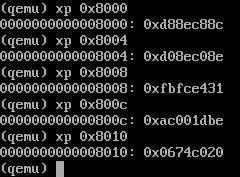
下圖中,筆者利用qemu提供的xp工具將0x8000-0x8010的內容dump出來,用以跟上圖0x200-0x210比對,比較上、下這兩張圖,可以證明作業系統程式碼正確地被載入至0x8000。
 |
【Reference】
2. Jserv's Blog
3. X86 開機流程小記
5. linux-source-2.6.31
2010年8月3日 星期二
[打造簡易作業系統 - 以GNU Assembler組合語言撰寫] (一) 開機Hello World實例
小弟最近想嘗試利用GAS(GNU Assembler)組合語言撰寫非常小型的作業系統,本篇文章說明如何利用GAS組合語言在終端機上印出Hello World.
簡介x86 CPU開機流程
x86 CPU開機後,首要之事會先跳至0xFFFF0執行BIOS ROM的程式,當BIOS測試程序通過後,BIOS便會把執行權交給下一個程式 (boot loader或一支小程式),BIOS會將該程式
(通常為一個磁區[Sector]大小,即512 bytes)載入記憶體0x7C00位置,並跳至0x7C00執行該段程式碼。該磁區被稱為MBR,BIOS會檢查該磁區最後兩個位完組必須為0x55AA,否則該磁區該被視為無效的MBR。
所以,首要之事就是利用GAS撰寫一支大小為512位元組的二進位檔 (Binary File),此檔需具備底下功能:
Compile and Link
以"gcc -c"將.S組合語言轉為成object file
再經由ld連結器將此object轉換成plain binary file
利用xxd工具觀察helo.bin格式 (以十六進制)
接著,使用qemu驗證hello.bin

為了讓此範例更真實,筆者有一台機器備有CF Card,將hello.bin透過dd工具寫進此CF Card最前面的512 bytes, 命令如下:
將該系統重開並選擇CF Card開機,其畫面如下:

【Reference】
1.30天打造OS!作業系統自作入門
2. Jserv's Blog
3. X86 開機流程小記
4. Linux assemblers: A comparison of GAS and NASM
簡介x86 CPU開機流程
x86 CPU開機後,首要之事會先跳至0xFFFF0執行BIOS ROM的程式,當BIOS測試程序通過後,BIOS便會把執行權交給下一個程式 (boot loader或一支小程式),BIOS會將該程式
(通常為一個磁區[Sector]大小,即512 bytes)載入記憶體0x7C00位置,並跳至0x7C00執行該段程式碼。該磁區被稱為MBR,BIOS會檢查該磁區最後兩個位完組必須為0x55AA,否則該磁區該被視為無效的MBR。
所以,首要之事就是利用GAS撰寫一支大小為512位元組的二進位檔 (Binary File),此檔需具備底下功能:
- 檔案系統,如: FAT12, FAT16, FAT32, NTFS等等。
- 利用BIOS中斷號碼0x10將資料寫至螢幕。
- 在最後兩個位元組寫入0x55AA以便通過BIOS識別。
    .code16


    .section .text

    .global main

main:

    # FAT12 file system format

    jmp       start_prog       # jmp instruction

    .byte     0x90

    .ascii    "ADRIAN  "       # OEM name (8 bytes)

    .word     512              # Bytes per sector

    .byte     1                # Sector per cluster

    .word     1                # Reserved sector count: should be 1 for FAT12

    .byte     2                # Number of file allocation tables.

    .word     224              # Maximum number of root directory entries.

    .word     2880             # Total sectors

    .byte     0xf0             # Media descriptor:

    .word     9                # Sectors per File Allocation Table

    .word     18               # Sectors per track

    .word     2                # Number of heads

    .long     0                # Count of hidden sectors

    .long     2880             # Total sectors: 18 (sectors per track) * 2 (heads) * 80 (sectors) = 2880

    .byte     0                # Physical driver number

    .byte     0                # Reserved

    .byte     0x29             # Extended boot signature

    .long     0x12345678       # Serial Number

    .ascii    "HELLO-OS   "    # Volume Label

    .ascii    "FAT12   "       # FAT file system type

    .fill     18, 1, 0         # fill 18 characters with zero


start_prog:

    movw    $0, %ax            # Initialize register

    movw    %ax, %ss

    movw    %ax, %ds

    movw    %ax, %es


    movw    $msg, %si          # move the address of msg to SI


loop:

    movb    $0xe, %ah

    movb    (%si), %al        # move the first character of msg to AL register

    cmpb    $0, %al

    je      fin

    int     $0x10             # write the specific character to console

    addw    $1, %si

    jmp     loop


fin:

# do nothing


msg:

    .ascii "Hello, World! This is Adrian Huang."

    .byte   0


    .org    0x1FE, 0x00       # fill the rest of characters with zero until the 254th character


# Boot sector signature

    .byte     0x55

    .byte     0xaa
Compile and Link
以"gcc -c"將.S組合語言轉為成object file
adrian@adrian-desktop:~/working/build_os/my_ex/02day/helloos4$ ls

hello.S

adrian@adrian-desktop:~/working/build_os/my_ex/02day/helloos4$ gcc -c hello.S

adrian@adrian-desktop:~/working/build_os/my_ex/02day/helloos4$ file hello.o

hello.o: ELF 64-bit LSB relocatable, x86-64, version 1 (SYSV), not stripped

adrian@adrian-desktop:~/working/build_os/my_ex/02day/helloos4$
再經由ld連結器將此object轉換成plain binary file
$ ld -Ttext=0x7C00 hello.o -o hello.bin --oformat binary

$ file hello.bin

hello.bin: DOS floppy 1440k, x86 hard disk boot sector
利用xxd工具觀察helo.bin格式 (以十六進制)
adrian@adrian-desktop:~/working/build_os/my_ex/02day/helloos4$ xxd hello.bin

0000000: eb4e 9041 4452 4941 4e20 2000 0201 0100  .N.ADRIAN  .....

0000010: 02e0 0040 0bf0 0900 1200 0200 0000 0000  ...@............

0000020: 400b 0000 0000 2978 5634 1248 454c 4c4f  @.....)xV4.HELLO

0000030: 2d4f 5320 2020 4641 5431 3220 2020 0000  -OS   FAT12   ..

0000040: 0000 0000 0000 0000 0000 0000 0000 0000  ................

0000050: b800 008e d08e d88e c0be 6b7c b40e 8a04  ..........k|....

0000060: 3c00 7407 cd10 83c6 01eb f148 656c 6c6f  <.t........Hello

0000070: 2c20 576f 726c 6421 2054 6869 7320 6973  , World! This is

0000080: 2041 6472 6961 6e20 4875 616e 672e 0000   Adrian Huang...

0000090: 0000 0000 0000 0000 0000 0000 0000 0000  ................

00000a0: 0000 0000 0000 0000 0000 0000 0000 0000  ................

00000b0: 0000 0000 0000 0000 0000 0000 0000 0000  ................

00000c0: 0000 0000 0000 0000 0000 0000 0000 0000  ................

00000d0: 0000 0000 0000 0000 0000 0000 0000 0000  ................

00000e0: 0000 0000 0000 0000 0000 0000 0000 0000  ................

00000f0: 0000 0000 0000 0000 0000 0000 0000 0000  ................

0000100: 0000 0000 0000 0000 0000 0000 0000 0000  ................

0000110: 0000 0000 0000 0000 0000 0000 0000 0000  ................

0000120: 0000 0000 0000 0000 0000 0000 0000 0000  ................

0000130: 0000 0000 0000 0000 0000 0000 0000 0000  ................

0000140: 0000 0000 0000 0000 0000 0000 0000 0000  ................

0000150: 0000 0000 0000 0000 0000 0000 0000 0000  ................

0000160: 0000 0000 0000 0000 0000 0000 0000 0000  ................

0000170: 0000 0000 0000 0000 0000 0000 0000 0000  ................

0000180: 0000 0000 0000 0000 0000 0000 0000 0000  ................

0000190: 0000 0000 0000 0000 0000 0000 0000 0000  ................

00001a0: 0000 0000 0000 0000 0000 0000 0000 0000  ................

00001b0: 0000 0000 0000 0000 0000 0000 0000 0000  ................

00001c0: 0000 0000 0000 0000 0000 0000 0000 0000  ................

00001d0: 0000 0000 0000 0000 0000 0000 0000 0000  ................

00001e0: 0000 0000 0000 0000 0000 0000 0000 0000  ................

00001f0: 0000 0000 0000 0000 0000 0000 0000 55aa  ..............U.
接著,使用qemu驗證hello.bin
為了讓此範例更真實,筆者有一台機器備有CF Card,將hello.bin透過dd工具寫進此CF Card最前面的512 bytes, 命令如下:
adrian@adrian-mem1:~/img$ sudo dd if=./hello.bin of=/dev/sda

[sudo] password for adrian:

1+0 records in

1+0 records out

512 bytes (512 B) copied, 0.00124243 s, 412 kB/s

adrian@adrian-mem1:~/img$
將該系統重開並選擇CF Card開機,其畫面如下:
【Reference】
1.30天打造OS!作業系統自作入門
2. Jserv's Blog
3. X86 開機流程小記
4. Linux assemblers: A comparison of GAS and NASM
2010年3月19日 星期五
簡介Linux Block I/O Layer (三) - I/O Path
此系列文章最後講解Block I/O Layer I/O Path運作原理。圖一為I/O Path簡易圖,檔案系統核心經由submit_bio函式將該bio交給Block I/O Layer的generic_make_request和__generic_make_request函式,緊接著呼叫__make_request_fn callback函式 (對應至__make_request()),此函式主要目的用來檢查此bio是否可以跟尚未處理的request結構的bio成員結合在一起 (merge),如果不行的話,則另外配置一個新的request結構並將其bio安插至該reqeust結構,再將該request交給I/O Scheduler,最後Block I/O Layer經由request_fn() callback function將待處理的request交給SCSI子系統。

圖一、Block I/O Layer之I/O Path簡易圖
下圖二為Linux Block I/O Layer核心I/O Path示意圖,此圖以ReiserFS為例,此圖對每個函式有詳細的解釋,所以在此不再解釋,請參照圖二。

圖二、Block I/O Layer之I/O Path
【Reference】
1. Linux Device Driver, third edition
2. Linux Kernel Source 2.6.31
3. Request-based Device-mapper multipath and Dynamic load balancing
4. Understanding the Linux Kernel, Third Edition - Chapter 14. Block Device Drivers
2010年3月18日 星期四
簡介Linux Block I/O Layer (二) - 探討BIO (Block I/O) and Request 結構
上一篇文章簡單介紹page, bio和request結構的定位,本篇文章著重於探討bio與request結構是如何串起來的。底下將分別介紹reqeust queue、request、bio與bio_vec等資料結構。首先,下圖展示這四個資料結構的關係。

Request Queue
Request Queue用來將待處理的request串成一個雙向的鏈結串列,此結構 (struct request_queue)定義在include/linux/blkdev.h檔頭檔。
Request
一個request資料結構,即表示一次block I/O傳輸請求。結構裡的queuelist便是將整個request串起來的成員,bio成員代表該request所欲傳輸block I/O個數,buffer成員代表當前資料傳輸的buffer區塊。request資料結構裡還有許多其它成員,詳見include/linux/blkdev.h標頭檔。
BIO (Block I/O)
當block I/O layer上層 (可參考此篇文章的圖,Ex: 檔案系統或虛擬記憶體子系統)欲傳輸某一區塊時,該層便會產生一個bio結構並交由Block I/O Layer,Block I/O Layer將新請求的bio併入現有的request結構裡 (前提是該request結構裡的bio所欲傳輸的區塊磁區剛好跟新請求的bio所欲傳輸的區塊磁區相近,如此變能發揮更大的傳輸效益),或者產生一個新的request結構並將此bio併入此request結構,此結構 (struct request_queue)定義在include/linux/bio.h標頭檔。
bio_vec (BIO Vector)
bio結構裡有一個稱為bi_io_vec一維陣列的成員,該陣列成員紀錄欲傳輸的資料緩衝區在記憶體何處。
【Reference】
1. Linux Device Driver, third edition
2. Linux Kernel Source 2.6.31
3. Request-based Device-mapper multipath and Dynamic load balancing
4. Understanding the Linux Kernel, Third Edition - Chapter 14. Block Device Drivers
簡介Linux Block I/O Layer (一) - Page, BIO (Block I/O) and Request 結構意義
Linux Block I/O Layer主要處理上層檔案系統的請求,進而將該請求往丟至低層的low-level device driver (例如: Linux SCSI Subsystem),下圖展示出這三層的關係,由圖中可知檔案系統驅動程式主要以page結構來描述所欲存取的資料在哪裡, 接著檔案系統驅動程式將page結構轉換bio (Block I/O),並經由submit_bio函式將該請求送至Block I/O Layer,該層主要任務便將bio結構轉換成request結構 (往後會有幾篇探討該層運作細節),並將該request結構丟至low-level device driver,以上是簡單的介紹.

【Reference】
1. Linux Device Driver, third edition
2. Linux Kernel Source 2.6.31
3. Request-based Device-mapper multipath and Dynamic load balancing

【Reference】
1. Linux Device Driver, third edition
2. Linux Kernel Source 2.6.31
3. Request-based Device-mapper multipath and Dynamic load balancing
2010年3月15日 星期一
C語言malloc之sizeof使用技巧
C語言程式設計師使用結構指標時,在配置一塊記憶體時通常都會使用下列宣告描述 (粗體字):
另一種寫法可以將程式碼簡化,將sizeof(struct abc)改成sizeof(*ptr),如下所示:
提供給各位參考.
struct abc {
char *ptr;
int var[20];
struct abc *next;
};
struct abc *ptr = (struct abc *) malloc(sizeof(struct abc));
另一種寫法可以將程式碼簡化,將sizeof(struct abc)改成sizeof(*ptr),如下所示:
struct abc *ptr = malloc(sizeof(*ptr));
提供給各位參考.
訂閱:
文章 (Atom)