顯示具有 GDT 標籤的文章。 顯示所有文章

2010年12月21日 星期二

[打造簡易作業系統 - 以GNU Assembler組合語言撰寫] (七) 利用Call Gate與TSS (Task-State Segment)實現特權等級的轉換

上篇文章僅介紹如何利用Call Gate,文中並未提及如何實現特權等級的轉換,也就是從低特權等級進入高特權等級,就如同Linux的user space (Privilege 3或稱Ring 3)進入kernel space (Privilege 0或稱Ring 0)。

簡介TSS (Task-State Segment)
本文僅簡單說明TSS在本文被使用的地方,如欲詳盡說明請參考[2]之第七章。

Task Structure
Figure 1為一個工作任務 (Task)的結構圖,一個工作任務分為兩大部份: 1. 工作任務的執行空間 (Task Execution Space),其中包含CS、SS以及若干個DS,也就是Figure 1右上角的三個區段。2. TSS: 由工作任務執行空間與一個儲存空間 (用來儲存工作任務的狀態)所組成。Figure 1又說明另一件事: TSS的Segment Selector必須儲存在Task Register。因此在使用TSS之前,必須使用LTR指令將TSS之Segment Selector載入至Task Register。

Figure 1 Structure of a Task

TSS Memory Layout

Figure 2為32位元TSS記憶體空間配置圖,如下所述:
  • ESP0、SS0、ESP1、SS1、ESP2與SS2: 分別為特權等級0、1與2的堆疊區段與堆疊指標,也就是Figure 1右下角三個 "Stack Seg. Priv. Level x"。本文利用ESP0與SS0實現特權等級的轉換 (Ring 3轉換至Ring 0),因此作者僅設定TSS的這兩個欄位,其它欄位則設為0。
  • 其它欄位在此不進一步探討,有興趣的網友可以參考[2]。

Figure 2 TSS Memory Layout

原始碼下載
由於篇幅的關係,往後該系列文章將不張貼程式碼,將提供連結下載方式,原始碼下載點


作業系統程式碼說明
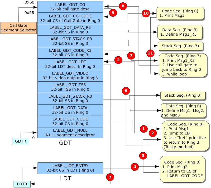
Figure 3為作業系統程式碼解說圖,此圖說明GDT與LDT的記憶體配置圖與程式流程圖,其流程圖並非以傳統方式表示。取而代之,改以紅色圈圈的數字代表程式流程並搭配GDT與LDT記憶體配置圖,如此更能清楚地明白程式執行流程。底下將針對每一步驟 (紅色圈圈的數字)做詳盡的解釋:

Figure 3 High Level Perspective of OS code

  1. 使用ljmp指令由真實模式轉換至32位元保護模式 (Ring 0)。其片段程式碼如下所示:
    
      /* Jump to protected-mode OS code        *
       * ljmpl prototype:                      *
       *   ljmpl segment_selector_of_CS offset */
      ljmpl     $SegSelectorCode32, $0

    此區段程式碼將Msg1輸出至螢幕,並將LDT的segment selector載入至LDTR,接著使用lcall指令跳至LDT的CS,如下所示:
        /* Load LDT selector */
       mov     $(SegSelectorLDT), %ax
    
       /* Load LDT selector in GDT to LDT register */
       lldt     %ax
    
       /* Jump to code segment in LDT */
       lcall     $(SegSelectorLDTCode32), $0
    
  2. 如第1點所述。
  3. 如第1點所述。
  4. 輸出Msg2,隨即使用lret指令返回LABEL_GDT_CODE。
  5. 通常,call與ret指令必須配合使用。執行call指令時,處理器會將SS、ESP、CS與EIP推入(Push) 該執行空間的堆疊 (Stack)。接著,執行ret指令時,處理器會將EIP、CS、ESP與SS從堆疊取出 (Pop)。為了實現從Ring 0返回Ring 3,底下程式碼模擬處理器的工作: 將Ring 3的SS、ESP、CS與EIP推入(Push) 該執行空間的堆疊 (Stack)並使用lret指令返回Ring 3。
       pushl    $(SegSelectorStackR3)
      pushl    $(TopOfStackR3)
      pushl    $(SegSelectorCodeR3)
      pushl    $0
      lret
    
  6. 從Ring 0 (LABEL_GDT_CODE)返回 Ring 3 (LABEL_GDT_CODE_R3)。
  7. 此Ring 3程式區段將Msg1_R3輸出至螢幕,利用call gate並搭配TSS成功地返回Ring 0程式區段。因此,必須設定TSS之ESP0與SS0欄位,如下所示:
    LABEL_TSS:
     .4byte  0                         /* Previous Task Link   */
     .4byte  TopOfStackR0              /* ESP0                 */
     .4byte  SegSelectorStackR0        /* SS0                  */
     .4byte  0                         /* ESP1                 */
     .4byte  0                         /* SS1                  */
     .4byte  0                         /* ESP2                 */
     .4byte  0                         /* SS2                  */
     .4byte  0                         /* CR3 (PDBR)           */
     .4byte  0                         /* EIP                  */
     .4byte  0                         /* EFLAGS               */
     .4byte  0                         /* EAX                  */
     .4byte  0                         /* ECX                  */
     .4byte  0                         /* EDX                  */
     .4byte  0                         /* EBX                  */
     .4byte  0                         /* ESP                  */
     .4byte  0                         /* EBP                  */
     .4byte  0                         /* ESI                  */
     .4byte  0                         /* EDI                  */
     .4byte  0                         /* ES                   */
     .4byte  0                         /* CS                   */
     .4byte  0                         /* SS                   */
     .4byte  0                         /* DS                   */
     .4byte  0                         /* FS                   */
     .4byte  0                         /* GS                   */
     .4byte  0                         /* LDT Segment Selector */
     .2byte  0                         /* Reserved             */
     .2byte  (. - LABEL_TSS + 2)       /* I/O Map Base Address */
    .set TSSLen, (. - LABEL_TSS)
    
    在此,特別對特權等級轉換做進一步解釋,以便讓讀者了解為什麼只要設定ESP0與SS0欄位即可。當存取目的程式區段 (Destination Code Segment)是被允許的,處理器便會根據Call Gate Descriptor的Segment Selector欄位找出對應的程式區段,如果又涉及特權等級轉換,處理器會將原本使用中的堆疊切換至目標特權等級的堆疊。舉例來說,假設目前程式區段運行於Ring 3,處理器便使用Ring 3的堆疊,當使用Call Gate欲轉換至Ring 0的程式區段。如果此要求是被允許的,則處理器會跳至Ring 0的程式區段並使用Ring 0的堆疊,因此程式設計員必須先設定Ring 0堆疊 (ESP0與SS0),這就是為什麼必須設定TSS的ESP與SS0欄位的原因。
  8. 跳至GDT之Call Gate的描述子 (Descriptor)。
  9. 根據Call Gate描述子的Segment Selector欄位找出對應的CS。
  10. 將Msg3輸出至螢幕並返回。
  11. 返回Ring 3程式區段,並執行一無窮迴圈。
QEMU測試結果

【Reference】
[1] Solrex - 使用開源軟體-自己動手寫作業系統
[2] Intel 64 and IA-32 Architectures. Software Developer's Manual. Volume 3A
[3] 30天打造OS!作業系統自作入門
[4] Jserv's Blog
[5] X86 開機流程小記
[6] Linux assemblers: A comparison of GAS and NASM
[7] linux-source-2.6.31

2010年12月8日 星期三

[打造簡易作業系統 - 以GNU Assembler組合語言撰寫] (六) 簡介Call Gate

Call Gate主要目的用來將一程式的特權等級 (Privilege Level) 轉換至另一個特權等級。舉例來說,Linux使用者利用ioctl()系統呼叫從user space (Privilege 3)進入kernel space (Privilege 0)。

Note
本篇範例程式僅示範如何使用call gate,並如何利用call gate呼叫所對應的程式碼片段,所有的程式碼都運行於privilege 0。對於特權等級的轉換 (Privilege 3 -> Privilege 0),留待往後的文章再詳加探討。本篇文章僅簡單地介紹Call Gate,詳盡介紹請參考Intel 64 and IA-32 Architectures. Software Developer's Manual. Volume 3A之5.8節。

Call-Gate Descriptor之介紹
參考Figure 1,其欄位如下所述:
  1. Offset: 代表所指定的程式區段 (Code Segment)進入點 (Entry Point),通常都設為0。
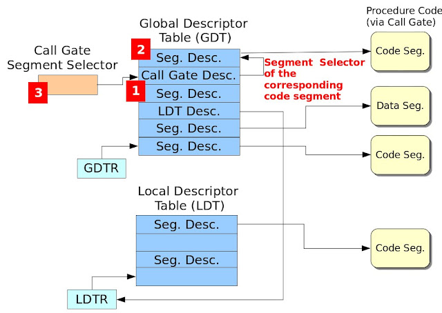
  2. Segment Selector: 此區段選擇器指定所要存取的程式區段 (Code Segment)。如此說明或許有點模糊,請參考Figure 2,此圖紅色數字方塊展示出設定Call Gate的必要程序,因此設定Call Gate需要三道步驟:A. 設定Call Gate Descriptor相關欄位,其欄位設定值如Table 1所示。B. 設定對應之程式區段。C. 設定Call-Gate之區段選擇器。
  3. Param. Count: 指定呼叫程序 (Calling Procedure)欲傳遞幾個參數給被呼叫的程序 (Called Procedure)。
  4. DPL (Descriptor Privilege Level): 此區段描述子之特權等級,其DPL與RPL特權等級之檢查請參考Intel 64 and IA-32 Architectures. Software Developer's Manual. Volume 3A之Figure 5-11。
  5. P: 此Call-Gate描述子是否有有效 (有效: P=1, 無效: P=0)。

Figure 1. Call-Gate Descriptor


Figure 2. Steps for Configuring Call Gate


Table 1. Field Value Configuration for Call-Gate Descriptor

Boot Loader程式碼
請參考此篇文章的"Boot Loader 程式碼"。

作業系統程式碼
Figure 3為作業系統程式碼,此作業系統程式碼運行於32位元保護模式,程式說明如下:

  1. 定義七個Segment Descriptor (LABEL_GDT_NULL、LABEL_GDT_CODE、LABEL_GDT_DATA、LABEL_GDT_VIDEO、LABEL_GDT_LDT、LABEL_GDT_CG_CODE與LABEL_GDT_CG)。其中VIDEO的基底位址為0xB8000,詳情請參考Printing to Screen。接著定義GDT的長度、定義Code、Data、VIDEO與LDT的segment selector、定義輸出的字串、定義GDTPtr與定義LDT表。
  2. LABEL_GDT_CG為Call Gate Descriptor,其儲存在GDT。此設定步驟為Figure 2的1號紅色方塊。
  3. LABEL_GDT_CG_CODE為Call Gate Descriptor欄位Segment Selector所指定的地方,也就是Call Gate所對應的區段程式碼。此設定步驟為Figure 2的2號紅色方塊。
/* os.S
*
*/

#include "pm.h"

.code16
.text
jmp os_main

# Segment descritors for GDT
LABEL_GDT_NULL: SEG_DESC 0, 0, 0
LABEL_GDT_CODE: SEG_DESC 0, (PECode32Len - 1), (DESC_ATTR_TYPE_CD_ER | DESC_ATTR_D)
LABEL_GDT_DATA: SEG_DESC 0, (DataLen - 1), (DESC_ATTR_TYPE_CD_RW)
LABEL_GDT_VIDEO: SEG_DESC 0xB8000, 0xFFFF, (DESC_ATTR_TYPE_CD_RW)
LABEL_GDT_LDT: SEG_DESC 0, (LDTLen - 1), (DESC_ATTR_TYPE_LDT)
LABEL_GDT_CG_CODE: SEG_DESC 0, (CG_CODE32_LEN - 1), (DESC_ATTR_TYPE_CD_ER | DESC_ATTR_D)
LABEL_GDT_CG: CALL_GATE SegSelectorCGCODE, 0, 0, (GATE_CG_ATTR)

# The length of GDT
.set GdtLen, (. - LABEL_GDT_NULL)

# Segment selectors
.set SegSelectorCode32, (LABEL_GDT_CODE - LABEL_GDT_NULL)
.set SegSelectorData, (LABEL_GDT_DATA - LABEL_GDT_NULL)
.set SegSelectorVideo, (LABEL_GDT_VIDEO - LABEL_GDT_NULL)
.set SegSelectorLDT, (LABEL_GDT_LDT - LABEL_GDT_NULL)
.set SegSelectorCGCODE, (LABEL_GDT_CG_CODE - LABEL_GDT_NULL)
.set SegSelectorCG, (LABEL_GDT_CG - LABEL_GDT_NULL)

# data segment
LABEL_DATA:
Msg1: .ascii "Welcome to Protect mode in GDT.\0"
Msg2: .ascii "Welcome to Protect mode in LDT.\0"
Msg3: .ascii "Welcome to Protect mode through Call Gate.\0"

.set Msg1Offset, (Msg1 - LABEL_DATA)
.set Msg2Offset, (Msg2 - LABEL_DATA)
.set Msg3Offset, (Msg3 - LABEL_DATA)

.set DataLen, (. - LABEL_DATA)

# GDTR pointer
LABEL_GDTR:
.2byte (GdtLen - 1) # Limit field
.4byte 0 # base field

# LDT information
LABEL_LDT:
LABEL_LDT_ENTRY: SEG_DESC 0, (LDT_CODE32_LEN - 1), (DESC_ATTR_TYPE_CD_E | DESC_ATTR_D)

# length of LDT
.set LDTLen, (. - LABEL_LDT)

# LDT selector
.set SegSelectorLDTCode32, (LABEL_LDT_ENTRY - LABEL_LDT + SA_TIL)


# real-mode OS code
os_main:
mov %cs, %ax
mov %ax, %ds
mov %ax, %ss
mov %ax, %es


/* Set gdt for code segment */
InitSegDescriptor LABEL_PE_CODE32, LABEL_GDT_CODE
InitSegDescriptor LABEL_DATA, LABEL_GDT_DATA
InitSegDescriptor LABEL_LDT, LABEL_GDT_LDT
InitSegDescriptor LABEL_PE_LDT_CODE32, LABEL_LDT_ENTRY
InitSegDescriptor LABEL_PE_CG_CODE32, LABEL_GDT_CG_CODE

/* Set GDTR */
xor %ax, %ax
mov %cs, %ax
shl $4, %eax
addl $LABEL_GDT_NULL, %eax
movl %eax, (LABEL_GDTR + 2)

/* Enable A20 line */
xor %ax, %ax
in $0x92, %al
or $2, %al
out %al, $0x92

cli

/* Load the GDT base address and limit from memory into the GDTR register */
lgdt LABEL_GDTR

/* Enable protect mode */
movl %cr0, %eax
orl $1, %eax
movl %eax, %cr0

/* Jump to protected-mode OS code */
ljmp $SegSelectorCode32, $0

LABEL_PE_CG_CODE32:
.code32
mov $(SegSelectorData), %ax
mov %ax, %ds
mov $(SegSelectorVideo), %ax
mov %ax, %gs

xorl %esi, %esi
xorl %edi, %edi
movl $Msg3Offset, %esi
movl $((80 * 11 + 0) * 2), %edi
movb $0xC, %ah

cg_dump_str:
lodsb
andb %al, %al
jz cg_fin
mov %ax, %gs:(%edi)
addl $2, %edi
jmp cg_dump_str

cg_fin:
lret

.set CG_CODE32_LEN, (. - LABEL_PE_CG_CODE32)

LABEL_PE_LDT_CODE32:
.code32
# invoke a procedure call throught a call-gate.
lcall $(SegSelectorCG), $0

mov $(SegSelectorData), %ax
mov %ax, %ds
mov $(SegSelectorVideo), %ax
mov %ax, %gs

xorl %esi, %esi
xorl %edi, %edi
movl $Msg2Offset, %esi
movl $((80 * 13 + 0) * 2), %edi
movb $0xC, %ah

ldt_dump_str:
lodsb
andb %al, %al
jz ldt_fin
mov %ax, %gs:(%edi)
addl $2, %edi
jmp ldt_dump_str

ldt_fin:
jmp .

.set LDT_CODE32_LEN, (. - LABEL_PE_LDT_CODE32)

# protected-mode OS code in GDT
LABEL_PE_CODE32:
.code32
/* Load data segment selector */
mov $(SegSelectorData), %ax
mov %ax, %ds

/* Load Video segment selector */
mov $(SegSelectorVideo), %ax
mov %ax, %gs

/* Output the data */
xorl %esi, %esi
xorl %edi, %edi
movl $Msg1Offset, %esi
movl $((80 * 10 + 0) * 2), %edi
movb $0xC, %ah

dump_str:
lodsb
andb %al, %al
jz fin
mov %ax, %gs:(%edi)
addl $2, %edi
jmp dump_str

fin:
/* Load LDT selector */
mov $(SegSelectorLDT), %ax

/* Load LDT selector in GDT to LDT register */
lldt %ax

/* Jump to code segment in LDT */
ljmp $(SegSelectorLDTCode32), $0

.set PECode32Len, (. - LABEL_PE_CODE32)

.ascii "Welcome to OS context!"
.byte 0

.org 0x400, 0x41 # fill characters with 'A'. Sector 2


Figure 3. Operating System Code


pm.h標頭檔
/* pm.h
*
* Adrian Huang (adrianhuang0701@gmail.com)
*/
.macro SEG_DESC Base, Limit, Attr
.2byte (\Limit & 0xFFFF)
.2byte (\Base & 0xFFFF)
.byte ((\Base >> 16) & 0xFF)
.2byte ((\Attr & 0xF0FF) | ((\Limit >> 8) & 0x0F00))
.byte ((\Base >> 24) & 0xFF)
.endm

.macro InitSegDescriptor OFFSET GDT_SEG_ADDR
xor %ax, %ax
mov %cs, %ax
shl $4, %eax
addl $(\OFFSET), %eax
movw %ax, (\GDT_SEG_ADDR + 2)
shr $16, %eax
movb %al, (\GDT_SEG_ADDR + 4)
movb %ah, (\GDT_SEG_ADDR + 7)

.endm

.macro CALL_GATE SegSelector, Offset, ParamCount, Attr
.2byte (\Offset & 0xFFFF)
.2byte (\SegSelector)
.byte (\ParamCount)
.byte (\Attr)
.2byte ((\Offset >> 16) & 0xFFFF)
.endm

.set DESC_ATTR_TYPE_LDT, 0x82 /* LDT Segment */
.set DESC_ATTR_TYPE_CG, 0x8C /* Call-Gate Segment */
.set DESC_ATTR_TYPE_CD_ER, 0x9A /* Code segment with Execute/Read */
.set DESC_ATTR_TYPE_CD_E, 0x98 /* Code segment with Execute Only */
.set DESC_ATTR_TYPE_CD_RW, 0x92 /* Data segment with R/W */
.set DESC_ATTR_D, 0x4000 /* 32-bit segment */

/* Selector Attribute */
.set SA_TIL, 0x4
.set SA_RPL0, 0x0
.set SA_RPL1, 0x1
.set SA_RPL2, 0x2
.set SA_RPL3, 0x3

/* The attribute of call gate */
.set GATE_CG_ATTR, 0x8C


編譯程式碼
下圖為編譯的Makefile。
LD=ld
CC=gcc

all: boot_loader.bin

boot_loader.bin: boot_loader.o os.o
${LD} -Ttext=0x7C00 -s $< -o $@ --oformat binary ${LD} -Ttext=0x0 -s os.o -o os.bin --oformat binary cat os.bin >> $@

boot_loader.o:
${CC} -c boot_loader.S

os.o:
${CC} -c os.S

clean:
rm -f boot_loader.o os.o os.bin boot_loader.bin

其編譯訊息如下所示:
adrian@adrian-desktop:~/working/build_os/my_ex/blog/pe-call-gate-same-priv$ make clean all
rm -f boot_loader.o os.o os.bin boot_loader.bin
gcc -c boot_loader.S
gcc -c os.S
ld -Ttext=0x7C00 -s boot_loader.o -o boot_loader.bin --oformat binary
ld -Ttext=0x0 -s os.o -o os.bin --oformat binary
ld: warning: cannot find entry symbol _start; defaulting to 0000000000000000
cat os.bin >> boot_loader.bin
adrian@adrian-desktop:~/working/build_os/my_ex/blog/pe-call-gate-same-priv$


QEMU測試結果


【Reference】
[1] Solrex - 使用開源軟體-自己動手寫作業系統
[2] Intel 64 and IA-32 Architectures. Software Developer's Manual. Volume 3A
[3] 30天打造OS!作業系統自作入門
[4] Jserv's Blog
[5] X86 開機流程小記
[6] Linux assemblers: A comparison of GAS and NASM
[7] linux-source-2.6.31

2010年10月11日 星期一

[打造簡易作業系統 - 以GNU Assembler組合語言撰寫] (五) 使用Local Descriptor Table (LDT)

上篇文章使用Global Descriptor Table (GDT)儲存Code Segment (CS)與Data Segment (DS)的資訊,以便能在保護模式下成功地執行程式碼與存取資料。本篇說明如何設定LDT,以便能執行位於LDT的程式碼。

LDT之介紹
LDT實現作業系統多個程序功能 (multiple processes),其特色為各個程序有自己的位址空間彼此互不干擾,每個程序會有各自的LDT,當作業系統欲執行某一程序時,作業系統會找出其對應的LDT,以便能執行該程序。詳細資料請參考Local Descriptor Table

LDT相關設定
LDT設定分成兩大步驟如下所述:

1. 在GDT表裡設定一個LDT entry (Configure a LDT Entry in GDT)
參考Figure 1,其每個欄位所應設定值如Table 1所示:


Figure 1. Segment Descriptor


Table 1. LDT entry configuration in GDT

2. 設定LDT表

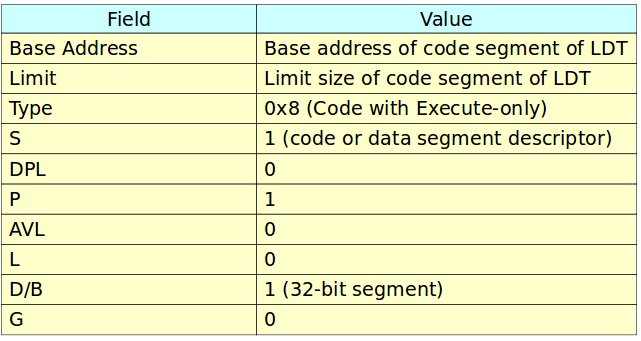
LDT表設定code segment/data segment相關資訊,其設定值如Table 2所示。


Table 2. LDT entry configuration in LDT

Boot Loader程式碼
請參考上篇文章的"Boot Loader 程式碼"。

作業系統程式碼
Figure 2為作業系統程式碼,此作業系統程式碼運行於32位元保護模式,一開始定義三個Segment Descriptor (NULL、CODE32、VIDEO與LDT),其中VIDEO的基底位址為0xB8000,詳情請參考Printing to Screen。接著定義GDT的長度、定義Code32、Data、VIDEO與LDT的segment selector、定義輸出的字串、定義GDTPtr與定義LDT表。

/* os.S
*
*/

#include "pm.h"

.code16
.text
jmp os_main

# Segment descritors for GDT
LABEL_GDT_NULL: SEG_DESC 0, 0, 0
LABEL_GDT_CODE: SEG_DESC 0, (PECode32Len - 1), (DESC_ATTR_TYPE_CD_ER | DESC_ATTR_D)
LABEL_GDT_DATA: SEG_DESC 0, (DataLen - 1), (DESC_ATTR_TYPE_CD_RW)
LABEL_GDT_VIDEO: SEG_DESC 0xB8000, 0xFFFF, (DESC_ATTR_TYPE_CD_RW)
LABEL_GDT_LDT: SEG_DESC 0, (LDTLen -1), (DESC_ATTR_TYPE_LDT)

# The length of GDT
.set GdtLen, (. - LABEL_GDT_NULL)

# Segment selectors
.set SegSelectorCode32, (LABEL_GDT_CODE - LABEL_GDT_NULL)
.set SegSelectorData, (LABEL_GDT_DATA - LABEL_GDT_NULL)
.set SegSelectorVideo, (LABEL_GDT_VIDEO - LABEL_GDT_NULL)
.set SegSelectorLDT, (LABEL_GDT_LDT - LABEL_GDT_NULL)

# data segment
LABEL_DATA:
Msg1: .ascii "Welcome to Protect mode in GDT.\0"
Msg2: .ascii "Welcome to Protect mode in LDT.\0"
Msg3: .ascii "This is signed by Adrian.\0"

.set Msg1Offset, (Msg1 - LABEL_DATA)
.set Msg2Offset, (Msg2 - LABEL_DATA)
.set Msg3Offset, (Msg3 - LABEL_DATA)

.set DataLen, (. - LABEL_DATA)

# GDTR pointer
LABEL_GDTR:
.2byte (GdtLen - 1) # Limit field
.4byte 0 # base field

# LDT information
LABEL_LDT:
LABEL_LDT_ENTRY: SEG_DESC 0, (LDT_CODE32_LEN - 1), (DESC_ATTR_TYPE_CD_E | DESC_ATTR_D)

# length of LDT
.set LDTLen, (. - LABEL_LDT)

# LDT selector
.set SegSelectorLDTCode32, (LABEL_LDT_ENTRY - LABEL_LDT + SA_TIL)


# real-mode OS code
os_main:
mov %cs, %ax
mov %ax, %ds
mov %ax, %ss
mov %ax, %es


/* Set gdt for code segment */
InitSegDescriptor LABEL_PE_CODE32, LABEL_GDT_CODE
InitSegDescriptor LABEL_DATA, LABEL_GDT_DATA
InitSegDescriptor LABEL_LDT, LABEL_GDT_LDT
InitSegDescriptor LABEL_PE_LDT_CODE32, LABEL_LDT_ENTRY

/* Set GDTR */
xor %ax, %ax
mov %cs, %ax
shl $4, %eax
addl $LABEL_GDT_NULL, %eax
movl %eax, (LABEL_GDTR + 2)

/* Enable A20 line */
xor %ax, %ax
in $0x92, %al
or $2, %al
out %al, $0x92

cli

/* Load the GDT base address and limit from memory into the GDTR register */
lgdt LABEL_GDTR

/* Enable protect mode */
movl %cr0, %eax
orl $1, %eax
movl %eax, %cr0

/* Jump to protected-mode OS code */
ljmp $SegSelectorCode32, $0


LABEL_PE_LDT_CODE32:
.code32
mov $(SegSelectorData), %ax
mov %ax, %ds
mov $(SegSelectorVideo), %ax
mov %ax, %gs

xorl %esi, %esi
xorl %edi, %edi
movl $Msg2Offset, %esi
movl $((80 * 11 + 0) * 2), %edi
movb $0xC, %ah

ldt_dump_str:
lodsb
andb %al, %al
jz ldt_fin
mov %ax, %gs:(%edi)
addl $2, %edi
jmp ldt_dump_str

ldt_fin:
jmp .

.set LDT_CODE32_LEN, (. - LABEL_PE_LDT_CODE32)

# protected-mode OS code in GDT
LABEL_PE_CODE32:
.code32
/* Load data segment selector */
mov $(SegSelectorData), %ax
mov %ax, %ds

/* Load Video segment selector */
mov $(SegSelectorVideo), %ax
mov %ax, %gs

/* Output the data */
xorl %esi, %esi
xorl %edi, %edi
movl $Msg1Offset, %esi
movl $((80 * 10 + 0) * 2), %edi
movb $0xC, %ah

dump_str:
lodsb
andb %al, %al
jz fin
mov %ax, %gs:(%edi)
addl $2, %edi
jmp dump_str

fin:
/* Load LDT selector */
mov $(SegSelectorLDT), %ax

/* Load LDT selector in GDT to LDT register */
lldt %ax

/* Jump to code segment in LDT */
ljmp $(SegSelectorLDTCode32), $0

.set PECode32Len, (. - LABEL_PE_CODE32)

os_msg:
.ascii "Welcome to OS context!"
.byte 0

.org 0x200, 0x41 # fill characters with 'A'. Sector 2


Figure 2. Code for Operating System

16位元real mode程式碼 (os_main)中,執行若干任務如下所述:
  1. 設定LABEL_GDT_CODE的基底位址為PE_CODE32的起始位址
  2. 設定LABEL_GDT_DATA的基底位址為LABEL_DATA的起始位址
  3. 設定LABEL_GDT_LDT的基底位址為LABEL_LDT的起始位址
  4. 設定LABEL_LDT_ENTRY的基底位址為LABEL_PE_LDT_CODE32的起始位址
  5. 設定GDTPtr的基底位址為GDT的起始位址(也就是GDT_DESC_NULL)
  6. 開啟A20線路 (A20 Line)
  7. 將GDT的起始位址載入至GDTR暫存器
  8. 設定cr0暫存器的bit 0以便進入保護模式
  9. 使用ljmp指令跳至PE_CODE32程式碼
  10. 使用lldt指令將LDT的segment selector載入至LDTR (Local Descriptor Table Register),並跳至SegSelectorLDTCode32 segment selector執行LDT的程式碼。
32位元保護模式程式碼 (LABEL_PE_CODE32)利用Video segment selector將"Welcome to Protect mode in GDT."顯示在螢幕上,而LABEL_PE_LDT_CODE32則將"Welcome to Protect mode in LDT."顯示在螢幕上,用以驗證程式運作之正確性。

pm.h標頭檔
/* pm.h
*
* Adrian Huang (adrianhuang0701@gmail.com)
*/
.macro SEG_DESC Base, Limit, Attr
.2byte (\Limit & 0xFFFF)
.2byte (\Base & 0xFFFF)
.byte ((\Base >> 16) & 0xFF)
.2byte ((\Attr & 0xF0FF) | ((\Limit >> 8) & 0x0F00))
.byte ((\Base >> 24) & 0xFF)
.endm

.macro InitSegDescriptor OFFSET GDT_SEG_ADDR
xor %ax, %ax
mov %cs, %ax
shl $4, %eax
addl $(\OFFSET), %eax
movw %ax, (\GDT_SEG_ADDR + 2)
shr $16, %eax
movb %al, (\GDT_SEG_ADDR + 4)
movb %ah, (\GDT_SEG_ADDR + 7)

.endm

.set DESC_ATTR_TYPE_LDT, 0x82 /* LDT Segment */
.set DESC_ATTR_TYPE_CD_ER, 0x9A /* Code segment with Execute/Read */
.set DESC_ATTR_TYPE_CD_E, 0x98 /* Code segment with Execute Only */
.set DESC_ATTR_TYPE_CD_RW, 0x92 /* Data segment with R/W */
.set DESC_ATTR_D, 0x4000 /* 32-bit segment */

/* Selector Attribute */
.set SA_TIL, 0x4
.set SA_RPL0, 0x0
.set SA_RPL1, 0x1
.set SA_RPL2, 0x2
.set SA_RPL3, 0x3


編譯程式碼
請參照此篇的Makefile程式碼

其編譯訊息如下所示:

adrian@adrian-desktop:~/working/build_os/my_ex/04day/blog/pe-multi-seg-ldt$ make clean all
rm -f boot_loader.o os.o boot_loader.bin
gcc -c boot_loader.S
gcc -c os.S
ld -Ttext=0x7C00 -s boot_loader.o -o boot_loader.bin --oformat binary
ld -Ttext=0x0 -s os.o -o os.bin --oformat binary
ld: warning: cannot find entry symbol _start; defaulting to 0000000000000000
cat os.bin >> boot_loader.bin
adrian@adrian-desktop:~/working/build_os/my_ex/04day/blog/pe-multi-seg-ldt$


QEMU測試結果


【Reference】
[1] Solrex - 使用開源軟體-自己動手寫作業系統
[2] Intel 64 and IA-32 Architectures. Software Developer's Manual. Volume 3A
[3] 30天打造OS!作業系統自作入門
[4] Jserv's Blog
[5] X86 開機流程小記
[6] Linux assemblers: A comparison of GAS and NASM
[7] linux-source-2.6.31

2010年9月29日 星期三

[打造簡易作業系統 - 以GNU Assembler組合語言撰寫] (四) 由16位元真實模式 (Real Mode) 進入32位元保護模式 (Protect Mode)

前三篇文章所展示的程式碼都是CPU執行於真實模式 (Real Mode)。然而,一般作業系統運行於保護模式 (Protect Mode),其記憶體定址最高可至4GB (32位元)。故本文先介紹real mode與protect mode記憶體定址的方式。

Real mode與Protect mode記憶體定址介紹
Figure 1展示real mode記憶體定址方式,其觀念在於將邏輯位址(Logical Address)的區段(Segment)位址向左位移4個位元,再將其所得的位址加上位移值,如此便能轉換成線性位址 (Linear Address)。至於,邏輯位址該如何表示呢? 其表示法為"Address of Segment:Offset"
,例如: CS:IP、SS:SP、DS:SI和ES:DI,詳情請參考x86 Assembly Language。Figure 1描述一個簡單邏輯位址轉換線性位址的例子,因此不再贅述。

Figure 1. Memory Segmentation in Real Mode

Figure 2展示保護模式記憶體定址方式,其觀念在於將區段 (Segment)看成區段選擇器 (Segment Selector),用此選擇器索引出對應的Segment Descriptor,如此便能索引32位元的基底位址 (32-bit base address),然後再加上位移植,便能轉換成線性位址。

Figure 2. Memory Segment in Protect Mode

保護模式相關課題之介紹
此段落將著重介紹保護模式相關課題之介紹,包含介紹GDT/LDT (GDTR/LDTR)、Segment Descriptor、Segment Selector、 和Memory Management Register

Global and Local Descriptor Table (GDT and LDT)
當CPU運行於保護模式時,所有的記憶體存取都必須經由GDT或LDT,此表格 (GDT or LDT)存放最小單元便是Segment Descriptor。每一個Segment Descriptor都有對應的segment selector,用以索引出對應的Segment Descriptor。

GDTR and LDTR (GDT Register and LDT Register)
GDTR與LDTR用以儲存GDT與LDT的起始位置,此設定必須在進入保護模式完成設定。Figure 3展示GDTR與LDTR格式,其中GDTR包含32位元的基底位址與16位元的長度限制。而LDTR多增加了16位元的segment selector。


Figure 3. Memory Management Register

Segment Descriptor
Segment Descriptor為Descriptor Table組成的基本元素,其長度為8位元組。如Figure 4所示,可分為三大類: 1. 32位元的基底位址 (Base Address), 2. 20位元的區段限制 (Segment Limit), 3. 區段屬性。細節請參考Intel 64 and IA-32 Architectures. Software Developer's Manual. Volume 3A


Figure 4. Segment Descriptor [2]

Segment Selector
Figure 5展示Segment Selector示意圖,其目的用來索引對應的Segment Descriptor。因Descriptor Index有13個位元,故Descriptor個數最大可至8192。


Figure 5. Segment Selector

Boot Loader程式碼
/* boot_loader.S
*
* Copyright (C) 2010 Adrian Huang (adrianhuang0701@gmail.com)
*
* This code is intended to simulate a simplified boot loader. This boot
* loader loads 3 sectors into the physical memory and jumps the entry
* point of OS.
*
*/

.code16
.text

.set BOOT_SEG, 0x07C0 /* starting code segment (CS) of boot loader */
.set OS_SEG, 0x0900 /* code segment address of OS entry point */
.set OS_OFFSET, 0x0000 /* the offset address of OS entry point */

.global _start
_start:
# FAT12 file system format
jmp start_prog # jmp instruction

.byte 0x90
.ascii "ADRIAN " # OEM name (8 bytes)
.word 512 # Bytes per sector
.byte 1 # Sector per cluster
.word 1 # Reserved sector count: should be 1 for FAT12
.byte 2 # Number of file allocation tables.
.word 224 # Maximum number of root directory entries.
.word 2880 # Total sectors
.byte 0xf0 # Media descriptor:
.word 9 # Sectors per File Allocation Table
.word 18 # Sectors per track
.word 2 # Number of heads
.long 0 # Count of hidden sectors
.long 0 # Total sectors
.byte 0 # Physical driver number
.byte 0 # Reserved
.byte 0x29 # Extended boot signature
.long 0x12345678 # Serial Number
.ascii "HELLO-OS " # Volume Label
.ascii "FAT12 " # FAT file system type
.fill 18, 1, 0 # fill 18 characters with zero

start_prog:
# initialize the register with cs register
movw %cs, %ax
movw %ax, %ds
movw %ax, %es
movw %ax, %ss
xorw %sp, %sp

cld # clear direction flag
sti # set interrupt flag

# The following code is loaded three sectors (2-4th sectors from boot.bin)
# into the physical memory 0x8000-0x85FF.
movw $OS_SEG, %ax
mov %ax, %es # ES:BX-> destination buffer address pointer
movw $OS_OFFSET, %bx
movb $2, %cl # sector


cont:
movb $0x02, %ah # Read sectors from drive
movb $0x1, %al # Sectors to read count
movb $0x0, %ch # track
movb $0x0, %dh # head
movb $0, %dl # drive

int $0x13 # trigger a interrupt 0x13 service
jc fail # the clear flag is set if the operation is failed

mov %es, %ax
addw $0x20, %ax # move to the next sector
movw %ax, %es # move to the next sector
incb %cl

cmpb $3, %cl # has finished reading 3 sectors?
jbe cont # continue to read the sector

jmp os_entry # jump to OS entry point

fail:
movw $err_msg, %si
fail_loop:
lodsb
andb %al, %al
jz end
movb $0x0e, %ah
int $0x10
jmp fail_loop


os_entry:
ljmp $OS_SEG, $OS_OFFSET # jump to os context

end:
hlt
jmp end

err_msg:
.ascii "Reading sectors operation is failed!"
.byte 0

.org 0x1FE, 0x41 # fill the rest of characters with zero until the 254th character

# Boot sector signature
.byte 0x55
.byte 0xaa


作業系統程式碼
此作業系統程式碼運行於32位元保護模式,一開始定義三個Segment Descriptor (NULL, CODE32與VIDEO),其中VIDEO的基底位址為0xB8000,詳情請參考Printing to Screen。接著定義GDT的長度、定義Code32與VIDEO的segment selector、定義GDTPtr。

16位元real mode程式碼 (os_main)中,執行若干任務如下所述:
  1. 設定Code32的基底位址為PE_CODE32的起始位址
  2. 設定GDTPtr的基底位址為GDT的起始位址(也就是GDT_DESC_NULL)
  3. 開啟A20線路 (A20 Line)
  4. 將GDT的起始位址載入至GDTR暫存器
  5. 設定cr0暫存器的bit 0以便進入保護模式
  6. 使用ljmp指令跳至PE_CODE32程式碼
32位元保護模式程式碼 (PE_CODE32)利用Video segment selector將'H'字元顯示在螢幕,用以驗證程式運作之正確性。

/* os.S
*
* Adrian Huang (adrianhuang0701@gmail.com)
*
* This code is OS context for protected-mode.
*
*/
#include "pm.h"

.code16
.text
jmp os_main

# Segment descritors for GDT
GDT_DESC_NULL: SEG_DESC 0, 0, 0
GDT_DESC_CODE32: SEG_DESC 0, (PECode32Len - 1), (DESC_ATTR_TYPE_CD_ER | DESC_ATTR_D)
GDT_DESC_VIDEO: SEG_DESC 0xB8000, 0xFFFF, (DESC_ATTR_TYPE_CD_RW)

# The length of GDT
.set GdtLen, (. - GDT_DESC_NULL)

# Segment selectors for code segment and video output
.set SegSelectorCode32, (GDT_DESC_CODE32 - GDT_DESC_NULL)
.set SegSelectorVideo, (GDT_DESC_VIDEO - GDT_DESC_NULL)

# GDTR pointer
GDTPtr:
.2byte (GdtLen - 1) # Limit field
.4byte 0 # base field

# real-mode OS code
os_main:
mov %cs, %ax
mov %ax, %ds
mov %ax, %ss
mov %ax, %es


/* Set gdt for code segment */
InitSegDescriptor PE_CODE32, GDT_DESC_CODE32

/* Set GDTR */
xor %ax, %ax
mov %cs, %ax
shl $4, %eax
addl $GDT_DESC_NULL, %eax
movl %eax, (GDTPtr + 2)

/* Enable A20 line */
xor %ax, %ax
in $0x92, %al
or $2, %al
out %al, $0x92

cli

/* Load the GDT base address and limit from memory into the GDTR register */
lgdt GDTPtr

/* Enable protect mode */
movl %cr0, %eax
orl $1, %eax
movl %eax, %cr0

/* Jump to protected-mode OS code */
ljmp $SegSelectorCode32, $0


# protected-mode OS code
PE_CODE32:
.code32
/* Load Video segment selector */
mov $(SegSelectorVideo), %ax
mov %ax, %gs

/* Output the data */
movl $((80 * 10 + 0) * 2), %edi
movb $0xC, %ah
movb $'H', %al
mov %ax, %gs:(%edi)

jmp .

.set PECode32Len, (. - PE_CODE32)

os_msg:
.ascii "Welcome to OS context!"
.byte 0

.org 0x200, 0x41 # fill characters with 'A'. Sector 2


pm.h標頭檔

/* pm.h
*
* Adrian Huang (adrianhuang0701@gmail.com)
*/


.macro SEG_DESC Base, Limit, Attr
.2byte (\Limit & 0xFFFF)
.2byte (\Base & 0xFFFF)
.byte ((\Base >> 16) & 0xFF)
.2byte ((\Attr & 0xF0FF) | ((\Limit >> 8) & 0x0F00))
.byte ((\Base >> 24) & 0xFF)
.endm

.macro InitSegDescriptor OFFSET GDT_SEG_ADDR
xor %ax, %ax
mov %cs, %ax
shl $4, %eax
addl $(\OFFSET), %eax
movw %ax, (\GDT_SEG_ADDR + 2)
shr $16, %eax
movb %al, (\GDT_SEG_ADDR + 4)
movb %ah, (\GDT_SEG_ADDR + 7)

.endm

.set DESC_ATTR_TYPE_LDT, 0x82 /* LDT Segment */
.set DESC_ATTR_TYPE_CD_ER, 0x9A /* Code segment with Execute/Read */
.set DESC_ATTR_TYPE_CD_E, 0x98 /* Code segment with Execute Only */
.set DESC_ATTR_TYPE_CD_RW, 0x92 /* Data segment with R/W */
.set DESC_ATTR_D, 0x4000 /* 32-bit segment */

/* Selector Attribute */
.set SA_TIL, 0x4
.set SA_RPL0, 0x0
.set SA_RPL1, 0x1
.set SA_RPL2, 0x2
.set SA_RPL3, 0x3

編譯程式碼
下圖為編譯的Makefile。
LD=ld
CC=gcc

all: boot_loader.bin

boot_loader.bin: boot_loader.o os.o
${LD} -Ttext=0x7C00 -s $< -o $@ --oformat binary
${LD} -Ttext=0x0 -s os.o -o os.bin --oformat binary
cat os.bin >> $@

boot_loader.o:
${CC} -c boot_loader.S

os.o:
${CC} -c os.S

clean:
rm -f boot_loader.o os.o os.bin boot_loader.bin


其編譯訊息如下所示:
adrian@adrian-desktop:~/working/build_os/my_ex/04day/pe-orig-makefile$ make all
gcc -c boot_loader.S
gcc -c os.S
ld -Ttext=0x7C00 -s boot_loader.o -o boot_loader.bin --oformat binary
ld -Ttext=0x0 -s os.o -o os.bin --oformat binary
ld: warning: cannot find entry symbol _start; defaulting to 0000000000000000
cat os.bin >> boot_loader.bin


QEMU測試結果


【Reference】
[1] Solrex - 使用開源軟體-自己動手寫作業系統
[2] Intel 64 and IA-32 Architectures. Software Developer's Manual. Volume 3A
[3] 30天打造OS!作業系統自作入門
[4] Jserv's Blog
[5] X86 開機流程小記
[6] Linux assemblers: A comparison of GAS and NASM
[7] linux-source-2.6.31